ABSTRACT
The most important target of this study is to develop a method to compare the materials’ degradation due to thermal fatigue and temperature variation between the carbon nanotube wire and unidirectional carbon fiber/epoxy composite (UCFEC). In the presented study, by using experimental results data, thermal fatigue life of carbon nanotube wire and unidirectional carbon fiber/epoxy was compared after being exposed to temperature variation in space. This process was done by using a new analytical method that models the material strength deterioration as a function of temperature variation in low Earth orbit thermal cycles. Based on the relations that were obtained by using recommended analytical method, the carbon nanotube wire offered less thermal fatigue strength degradation equal to 6.608% after being subjected to 1,200,000°C temperature variation in comparison with unidirectional carbon fiber/epoxy composite thermal fatigue strength degradation. Therefore, it seems that carbon nanotube wire shows better thermal fatigue resistance. The results of this comparison may be used to determine the suitable carbon material for space missions based on thermal fatigue life.
Key words: Carbon nanotube, low earth orbit, thermal cycles, temperature variation, material degradation.
Polymer materials can be used in many applications such as films, fibers, sheets, and coatings (Song et al., 2013). These forms may be applied to produce clothing, carpets, ropes, and reinforcements (Song et al., 2013). In application of carbon and nanomaterial, a few works are submitted by Saleh (2016, 2017, 2018), Saleh et al. (2017), and Gaddafi and Saleh (2017). Among the characteristics of carbon fibers, low densities, high thermal and chemical stabilities can be mentioned (Huang, 2009). This material can be applied in many industries such as aerospace, turbine blades, etc. Other characteristics of these materials are high strength and lightweight (Wilkerson et al., 2007). Furthermore, carbon fibers may be applied in composites to manufacture the flaps, aileron, and landing gear doors (Voicu, 2012). Further investigation on composite materials properties are also performed by Chow et al. (2016), Meszaros and Turcsan (2014), and Jo and Lee (2014).
Recently, unidirectional carbon fiber/epoxy composite (UCFEC) and carbon nanotube (CNT) wire have been applied in many industries like aerospace. To make sure that the aerospace structure is safe and reliable, fatigue life of UCFEC and CNT wire in space needs to be estimated because thermal fatigue in space is one of the important issues that affects space structures.Thermal fatigue occurs while thermal cycles exist. A great example for thermal fatigue in space is satellite that rotates around the planets. These satellites while rotating around the planets pass through the planets’ shadows which may be extremely cold, and sun illumination which is extremely hot. As a result of the full rotation around the planet, a thermal cycle appears to affect the structure.
These thermal cycles may cause crack initiation and propagation in aerospace structures. Thus, thermal fatigue analysis of space structures is really important to prevent crack initiation, propagation, and fracture in space environment. In order to predict the long-term durability, recently, “crack closure detection using photometrical analysis is submitted by Savkin et al. (2015) and “durability and integrity studies of environmentally conditioned interfaces in fibrous polymeric composite: critical concepts and comments” is provided by Ray and Rathore (2014).In assessment of the damage in different materials, “canary approach for monitoring BGA interconnect reliability under temperature cycling” is presented by Chauhan et al. (2012), “thermal fatigue and hypothermal atomic oxygen exposure behavior of carbon nanotube wire” is provided by Misak et al. (2013), and “determination of material parameters for discrete damage mechanics analysis of carbon-epoxy laminates” is developed by Barbero and Cosso (2014).
Furthermore, in the area of obtaining analytical evaluation methods for determining mechanical properties of different materials, a few works are submitted by Anvari (2014, 2016a, b, 2017a, b, c) and Adibnazari and Anvari (2017). Some of the cited studies have investigated the fatigue life of composite laminates. Nevertheless, it appears that there are a few works in this area that can clearly illustrate the thermal deterioration in CNT wire and UCFEC. In addition, it seems that there is no work to compare the thermal fatigue life of these two materials in space.In the presented research, by applying two experimental procedures and using a new analytical method, relations to predict the strength degradation of UCFEC in various temperature variations are achieved.
By using these relations, material strength degradation between CNT wire and UCFEC is compared. The results of this contribution can also be applied for estimation of strength of UCFEC in different temperature variations. Therefore, this analytical method might be helpful to predict the thermal life of UCFEC in space environment, especially in low earth orbit environment. In this study, the thermal resistance of UCFEC and CNT wire in low earth orbit is measured and compared with each other. It seems that this method is a novel approach of comparison sine it has not been used in any other works. According to this approach, material degradation is measured based on temperature variation which is applied to estimate the thermal fatigue life.
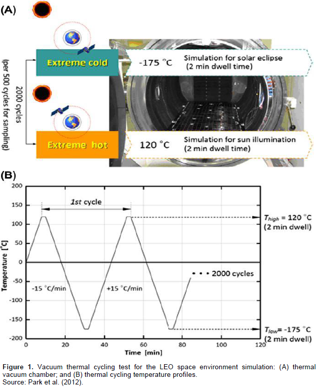
The experimental procedure (Park et al., 2012) that is mentioned in this study simulates the Low Earth Orbit (LEO) environment as satellite rotates around the earth as is illustrated in Figure 1. In this experiment, polyacrylonitrile (PAN)-based unidirectional Torayca carbon fibers in the form of prepeg tape is used (Park et al., 2012). The laminated composite panels were fabricated by stacking multiple layers of unidirectional prepregs. All prepregs had zero degree orientation at normal thicknesses of 1.0, 1.5 and 3.0 mm. Cure temperature and cycle times were 176.7°C for 180 min. A consolidation pressure was employed throughout the cure cycles with a full vacuum of 1 bar (107.9 kPa) (Park et al., 2012). The experiment was performed in an environmental chamber with a propotional integral derivative (PID) programmable temperature controller.

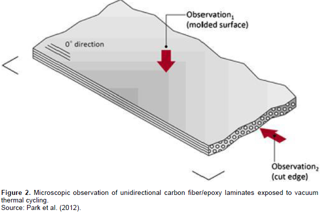
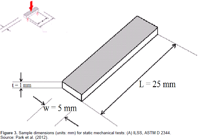
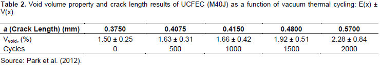
Test temperature range should be as large as possible to meet environmental stress screening (ESS) purposes based on the guideline in MIL-STD-810F (Park et al., 2012). This environment consists of vacuum thermal cycles of 120°C to -175°C and back to120°C (Park et al., 2012). 120°C is related to sun illumination and -175°C is related to solar eclipse (Park et al., 2012). For investigation of UCFEC mechanical properties deterioration due to low earth environment condition, 2000 thermal cycles have been performed in laboratory (Park et al., 2012). After this experiment, samples were cut and then dried in a vacuum oven at 60°C for 24 h to remove moisture (Park et al., 2012). The standard temperature and relative humidity used in this laboratory are 23 ± 2°C and 50 ± 5%, respectively (Park et al., 2012). The sample dimensions for static mechanical tests are shown in Figure 3. In UCFEC sample, all the carbon fibers are parallel imbedded in epoxy. The UCFEC sample is illustrated in Figure 2 (Park et al., 2012). In the following sections, the analytical method used to estimate the crack propagation of UCFEC in LEO environment is discussed.Void volume in UCFEC after being exposed to 0, 500, 1000, 1500, and 2000 thermal cycles is indicated in Table 2. With the application of data in Table 2, equation to estimate the void volume in UCFEC after being exposed to thermal cycles in LEO can be obtained. Furthermore, by application of derivative on void volume with respect to cycle numbers, void volume growth rate may be obtained. Due to this fact that in this experiment void volume growth occurs as a result of crack growth, this derivative may be able to predict crack growth rate in UCFEC sample in LEO environment.

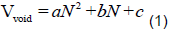
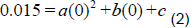
At the beginning of the simulation experiment (0 cycles), the void volume percent is equal to 0.015, therefore
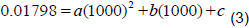
and at 1000 cycle, void volume percent is equal to 0.0166, thus
Furthermore, at 2000 cycles, the void volume percent in sample is, 0.0228. As a result
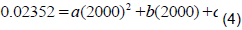
Thus, by solving the three equations ((2), (3), and (4)), three unknown quantities (a, b, and c), equation (5) is obtained that indicates the void volume percent in sample as a function of the cycle numbers. In Figure 4, void volume to total volume ratio in sample as a function of Cycle numbers in LEO simulation experiment is illustrated:

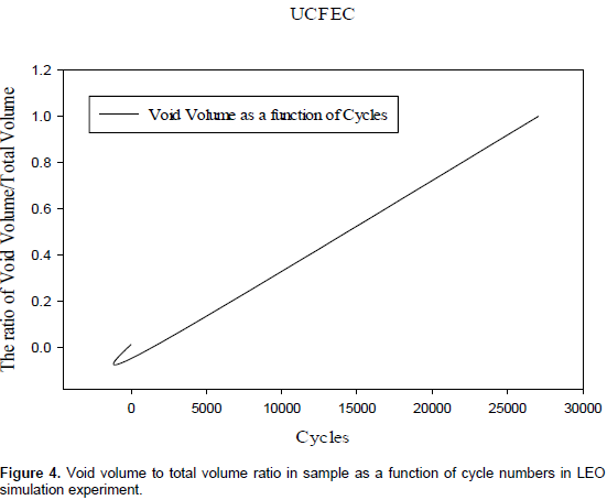
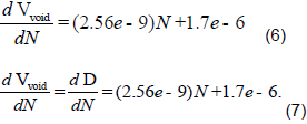
With the application of equation (5), obtaining void volume in any cycle number is possible. As an instance, in 3,000 and 4,000 thermal cycles, the void volume is equal to 0.03162 and 0.04228, respectively. By using partial derivative on equation (5), crack density growth rate estimation equation is obtained. The results of this derivative are indicated in equations (6) and (7).
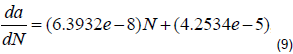
Continuing this approach and using the data in Table 2, a, which is the crack length equation as a function of thermal cycles is obtained. In this study, void volume percent is equal to crack length percent because the voids are induced due to the crack growth.
Thus, the crack growth rate relation can be defined as:
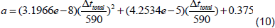
Because each cycle is temperature variation from 120 to -175°C and back to 120°C (Karadeniz, 2005), as a result, each cycle is equal to 590°C temperature variation. Thus, 1°C temperature variation is 1/590 of each cycle. In addition, Δt Celsius temperature variation may be determined as Δt/590. By imposing this result into equation (8), equation (10) can be achieved. Equation (10) indicates the crack length as a function of temperature variation
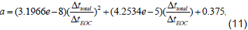
Moreover, because 590 is the temperature variation at Earth Orbit Cycle (EOC), therefore, it can be named as ΔtEOC. By substituting ΔtEOC into equation (10), the following equation (11) is obtained.
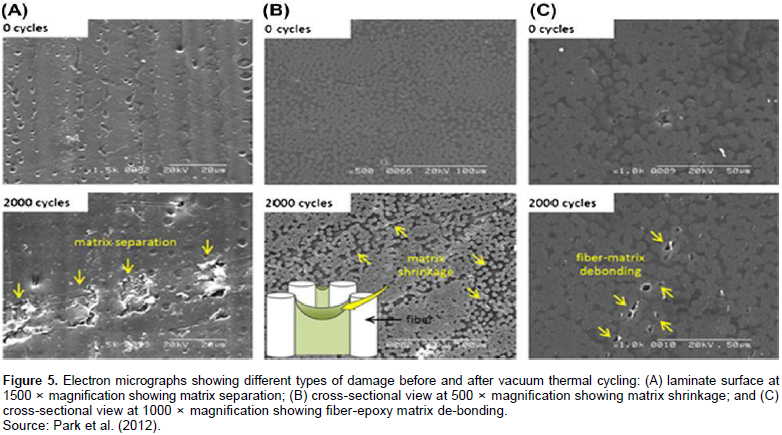
In Figure 5, UCFEC before and after being exposed to 2000 thermal cycles in earth orbit is illustrated. In sections A, B, and C of Figure 5, matrix separation, matrix shrinkage, and matrix de-bonding are shown, respectively. Matrix separation and fiber-matrix de-bonding can induce deterioration in UCFEC that may cause crack initiation, propagation and fracture due to thermal fatigue.

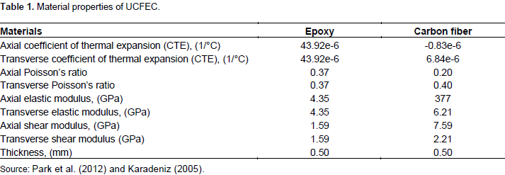
Convex curves method with application of least square approach
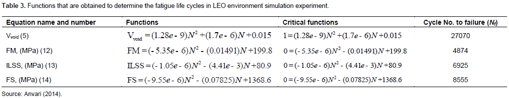
In this section, a method is introduced to estimate the thermal fatigue life of UCFEC in LEO environment condition. The data used to develop the equations representing convex curves (Anvari, 2014) with applying least square method, are exploited from an experimental procedure (Park et al., 2012). As it can be observed in Table 1, the amount of CTE values in carbon fiber is different from epoxy. This difference of CTEs between these two materials may cause different values of strain once the UCFEC is being heated or cooled. This difference of strains may cause interface stress between carbon fiber and epoxy. This process can lead to matrix separation or fiber-matrix de-bonding that cause deterioration in UCFEC due to thermal fatigue. In Table 3, functions that are obtained to determine the fatigue life cycles of UCFEC in LEO environment simulation experiment are indicated.

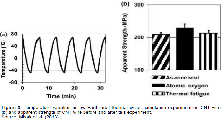
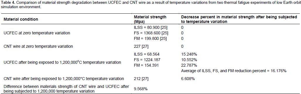
In the presented part of this study, the results of this research are compared with the results of another experiment (Misak et al., 2013). In the comparison of these two results, material strength as a function of temperature variation has been investigated. Both experiments are thermal fatigue experiments on UCFEC and CNT wire materials, respectively. For the first experiment (Park et al., 2012), a procedure to achieve the material strength as a function of temperature variation is introduced in this section and for the second experiment (Misak et al., 2013), data for CNT wire strength in two states of as-received and after being exposed to 1,200,000 temperature variation (5000 thermal cycles in low Earth orbit) are available from the experiment data (Misak et al., 2013). In Figure 6(b) (Misak et al., 2013), the remaining apparent strength for CNT wire after 5,000 thermal cycles with 240°C temperature variation at each of cycles is illustrated.

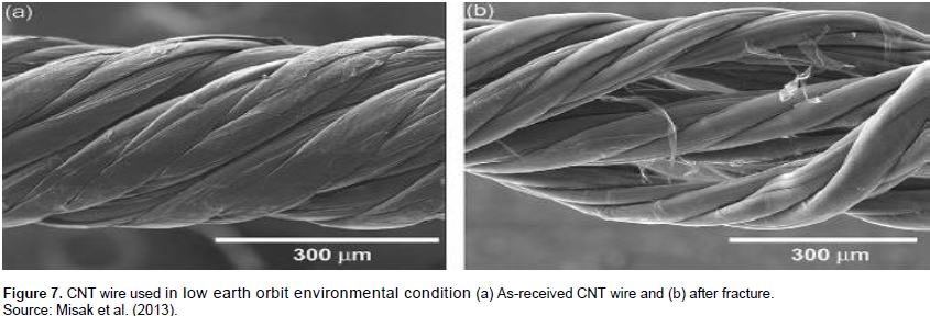
It seems that after these cycles, apparent strength of CNT wire is decreased from about 227 to 212 Mpa. That is 6.608% decrease in apparent strength. In order to convert these cycles to temperature variation, the following relation can be used: Δttotal = Δt.N, where Δttotal is the total temperature variations after the experiment, Δt is the temperature variation at each cycle (240°C temperature variation for the CNT wire experiment (Misak et al., 2013)) and N is the number of cycles for the experiment (5,000 cycles for the CNT wire experiment (Misak et al., 2013)). By using these assumptions and based on the mentioned relation, the total temperature variations after the thermal fatigue experiment becomes: 240*5000, that is equal to 1,200,000 temperature variations. In Figure 7, CNT wire used in low earth orbit environmental condition is shown.

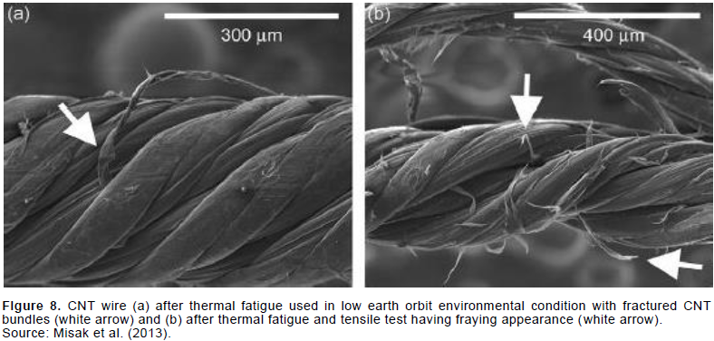
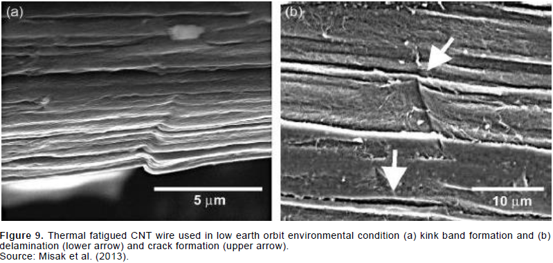
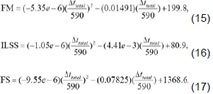
The numerical quantity of ∆ttotal that is obtained from the mentioned relation can be substituted into the following equations to predict the strength of UCFEC in first thermal fatigue experiment (Park et al., 2012). The amounts that are obtained from these relations can be applied to compare the results between the two thermal fatigue experiments. As it is obvious, this relation can contribute to compare the strength of CNT wire and UCFEC after being subjected to 1,200,000 temperature variations in low Earth orbit environment condition. Because each Earth orbit cycle is 590°C temperature variation in UCFEC experiment (Park et al., 2012), therefore, N= Δttotal/590. By substituting this relation into equations (12), (13), and (14), equations (15), (16), and (17) are achieved and can be used to compare the strength between the CNT wire and UCFEC after being exposed to 1,200,000 total temperature variations. The comparison results are indicated in Table 4. Moreover, as-received and thermal fatigued CNT wire are illustrated in Figures 8 and 9 (Misak et al., 2013).

In the presented research, by using two experimental procedures data that have been performed on UCFEC and CNT wire, and a new analytical method with the application of least square approach, equations are obtained to compare the material strength between the CNT wire and UCFEC after being subjected to vacuum thermal cycles in low Earth orbit environment simulation condition. The results of this study have indicated that after 1,200,000oC temperature variation in this condition, UCFEC has shown the average 9.568% more material strength degradation in comparison with CNT wire. Based on this process, it appears that CNT wire is a more durable material in vacuum thermal cycle’s conditions and UCFEC exhibits less strength stability in this environment condition. Therefore, it seems that CNT wire can represent a more life in low Earth orbit environment condition. Nevertheless, more analysis may be required to compare that which one of these materials are more cost-effective in different aerospace missions that they encounter to temperature variation cycles.
The author has not declared any conflict of interests.
The author would like to appreciate the guidance of advisors. All the funding related to this research is provided by the presented author.
REFERENCES
|
Adibnazari S, Anvari A (2017). Frictional effect on stress and displacement fileds in contact region. J. Mech. Eng. Res. 9(4):34-45.
Crossref
|
|
|
|
Anvari A (2014). Fatigue life prediction of unidirectional carbon fiber/epoxy composite in Earth orbit. Int. J. Appl. Math. Mech. 10(5):58-85.
|
|
|
|
|
Anvari A (2016). Fatigue life of unidirectional carbon fiber/epoxy in Earth orbit and Mars. 33rd annual RCAF conference, University of Missouri-Columbia, U.S.A.
|
|
|
|
|
Anvari A (2016). Friction coefficient variation with sliding velocity in copper with copper contact. Periodica Polytechnica, Mech. Eng. 60(3):137.
|
|
|
|
|
Anvari A (2017). Crack growth as a function of temperature variation in carbon fiber/epoxy. J. Chem. Eng. Mater. Sci. 8(3):17-30.
Crossref
|
|
|
|
|
Anvari A (2017). Effect of nano carbon percentage on properties of composite materials. J. Chem. Eng. Mater. Sci. 8(4):31-36.
|
|
|
|
|
Anvari A (2017). Failure of Nickel-base super alloy (ME3) in aerospace gas turbine engines. J. Chem. Eng. Mater. Sci. 8(6):46-65.
Crossref
|
|
|
|
|
Barbero EJ, Cosso FA (2014). Determination of Material Parameters for Discrete Damage Mechanics Analysis of Carbon-Epoxy Laminates. Composites: Part B 56:638-646.
Crossref
|
|
|
|
|
Chauhan P, Osternman M, Pecht M (2012). Canary Approach For Monitoring BGA Interconnect Reliability Under Temperature Cycling. CALCE Electronic Products and Systems Center, University of Maryland, College Park, MD 20742.
|
|
|
|
|
Chow WS, Leu YY, Ishak ZAM (2016). Mechanical, Thermal and Morphological Properties of Injection Molded Poly(Lactic acid)/Calcium Carbonate Nanocomposites. Periodica Polytechnica, Mech. Eng. 60(1):15-20.
|
|
|
|
|
Gaddafi ID, Saleh TA (2017). Effects of bimetallic Ce/Fe nanoparticles on the desulfurization of thiophenes using activated carbon. Chem. Eng. J. 307:914-927.
Crossref
|
|
|
|
|
Huang X (2009). Fabrication and Properties of Carbon Fibers. Materials 2:2369-2403.
Crossref
|
|
|
|
|
Jo HS, Lee GW (2014). Thermal Expansion Coefficient and Young's Modulus of Silica-Reinforced Epoxy Composite. Int. J. Chem. Mol. Nuclear Mater. Metallurg. Eng. 8(11):1188-1191.
|
|
|
|
|
Karadeniz ZH (2005). A numerical study on the thermal expansion coefficients of fiber reinforced composite materials. Master of Science Thesis in mechanical engineering, Energy Program, Dokuz Eylul University.
|
|
|
|
|
Meszaros L, Turcsan T (2014). Development and mechanical properties of carbon fibre reinforced EP/VE hybrid composite systems. Periodica Polytechnica, Mech. Eng. 58(2):127-133.
|
|
|
|
|
Misak HE, Sabelkin V, Mall S, Kladitis PE (2013). Thermal fatigue and hypothermal atomic oxygen exposure behavior of carbon nanotube wire. Carbon 57:42-49.
Crossref
|
|
|
|
|
Park SY, Choi HS, Choi WJ, Kwon H (2012). Effect of vacuum thermal cyclic exposures on unidirectional carbon fiber/epoxy composites for low earth orbit space applications. Composites: Part B 43:726-738.
Crossref
|
|
|
|
|
Ray BC, Rathore D (2014). Durability and integrity studies of environmentally conditioned interfaces in fibrous polymeric composites: Critical concepts and comments. Department of Metallurgical and Materials Engineering, National Institute of Technology, Rourkela-769008, India.
|
|
|
|
|
Savkin A, Andronik A, Abhilash R (2015). Crack Closure Detection Using Photometrical Analysis. Periodica Polytechnica Mech. Eng. 59(3):114-119.
Crossref
|
|
|
|
|
Song K, Zhang Y, Meng J, Green EC, Tajaddod N, Li H, Minus ML (2013). Structural Polymer-Based Carbon Nanotube Composite Fibers: Understanding the Processing Structure-Performance Relationship. Materials 6:2543-2577.
Crossref
|
|
|
|
|
Saleh TA (2016). Nanomaterials and polymer membranes: Synthesis, characterization, and applications. 1st edition.
|
|
|
|
|
Saleh TA (2017). Advanced nanomaterials for water engineering, treatment, and hydraulics.
Crossref
|
|
|
|
|
Saleh TA (2018). Nanotechnology in oil and gas industries: Principles and applications (Topics in mining, metallurgy and minerals engineering). 1st edition.
Crossref
|
|
|
|
|
Saleh TA, Alshaheri AH, Tahir MIM, Rahman MBA, Ravoof TBSA (2017). Catalytic oxidation of cyclohexane using transition metal complexes of dithiocarbazate Schiff base. Chem. Eng. J. 327:423-430.
Crossref
|
|
|
|
|
Voicu R (2012). Structural Characterization and Mechanical Behaviour of Carbon Fiber/epoxy Composite for Aeronautical Field. Materiale Plastice 49(1):34-40.
|
|
|
|
|
Wilkerson J, Daniel A, Daniel D (2007). Fatigue Characterization of Functionalized Carbon Nanotube Reinforced Carbon Fiber Composites. Texas A & M University, College Station, Texas 77844-3012.
Crossref
|
|