Full Length Research Paper

ABSTRACT
The main objective of this study is to investigate the effect of meteorites and debris impact on thermal fatigue life of unidirectional T700 carbon fiber/epoxy composite material. This composite material may be applied in space structures for space missions. These structures are exposed to thermal cycles as they go in and out of the planet’s shadow. If in this environmental condition, meteorites and debris impact with the structure, they may have effect on the thermal fatigue life of the structure. It means that the impact may decrease or increase the thermal cycles to failure of the structure in the presence of meteorite and/or debris. In this study, by applying experimental results and using analytical method attempt was made to estimate the thermal fatigue life in the presence of meteorite and/or debris impact, and thermal cycle condition. The results of this research can contribute to predict the thermal fatigue life in the presence of debris and/or meteorites impact to structure in possible future space missions. Furthermore, the results of this study have shown that the impact of debris and/or meteorites can increase the interlaminar shear stress between the T700 carbon fiber and epoxy which may result in crack formation and decrease the thermal fatigue life.
Key words: T700 carbon fiber, meteorite and debris, space structures, thermal fatigue life, impact effect, unidirectional composite.
INTRODUCTION
It has been decades that many industries such as automobile, sport goods, aerospace, etc., are applying composite materials in their productions (Fitzer et a., 1984; Tamilarasana et al., 2015; Petersson et al., 2013; Park et al., 2012). Currently, with the advancements in materials science and engineering, many industries are using nanocomposites because of their enhanced mechanical properties such as higher strength and lightweight in comparison with that of composite materials (Camargo et al., 2009; Tyagi and Tyagi, 2014; Okpala, 2013; Hussain et al., 2006).
However, thermal cycles can cause degradation of mechanical properties in composite materials. The reason is the mismatch between the coefficient of thermal expansion (CTE) between the fibers and matrix which cause stress concentration at fiber/matrix interface once the thermal cycles are applied to the composite material.
In applying analytical method to obtain new relations in order to estimate the mechanical properties of materials, “friction coefficient variation with sliding velocity in copper with copper contact” is submitted by Anvari (2016), “frictional effect on stress and displacement fields in contact region” is presented by Adibnazari and Anvari (2017), and “cycle numbers to failure for magnesium and its alloys in human body fluid” is investigated by Alijani and Anvari (2018). Furthermore, currently, “probabilistic fatigue assessment for high-speed railway axles due to foreign object damage” is provided by Wu et al. (2018).
Park et al. (2012) performed thermal fatigue experiments on Unidirectional Carbon Fiber/Epoxy Composite (UCFEC). The goal was to simulate the Low Earth Orbit (LEO) environmental condition to measure its effect on UCFEC. In LEO, satellites go in and out of earth’s shadow. Thus, the structure is exposed to thermal vacuum cycles. As the structure goes through the earth’s shadow, its temperature decreases to about -175°C, and as it is exposed to sun illumination, its temperature increases to 120°C. This experiment has been performed and the results indicated the effect of thermal vacuum cycles on mechanical properties of UCFEC in LEO.
The results of the thermal fatigue experiment on UCFEC in LEO simulation experiment was analyzed by Park et al. (2014). The analysis showed that Inter-Laminar Shear Strength (ILSS), Flexural Modulus (FM), and Flexural Strength (FS) of UCFEC decreased as the thermal cycles in LEO experiment simulation increased. Additionally, by performing the analysis on the results, it has been concluded that ILSS, FM, and FS decreased approximately by illustration of Convex Curves as thermal cycles increase. These convex curves were resembled; ILSS, FM, and FS as a function of thermal cycle numbers. Furthermore, by solving the convex curves equations for ILSS, FM, and FS while they were equal to zero, it has been determined that cycle numbers to failure for ILSS is less than that for FM and FS. According to these results from the analysis of the experiments, it appeared that failure of UCFEC is due to the degradation of ILSS in LEO simulation experiment.
In 2018 [14], the thermal analysis to obtain a relation for deriving the Inter-Laminar Shear stress (ILSs) in UCFEC due to thermal cycles has continued. The ana-lysis has shown that the ILSs seems to be proportional to three factors; first, the mismatch of Coefficient of Thermal Expansion (CTE) between the carbon fiber and epoxy (Δα). Second, the temperature variation from the stress free or crack free temperature of the UCFEC sample to environment temperature (ΔT). Third, the maximum shear modulus between the carbon fiber and epoxy (Gmax). Based on these assumptions, the following equation is developed. The following equation has been approved with the results obtained from research performed by Park et al. (2012).
ILSs= Δα. ΔT.Gmax (1)
Geng et al. (2018) in conducting experiments have determined that the value of CTE for T700 carbon fiber in the presence of thermal cycles and tensile load decreases. This valuable conclusion seems to be very useful to predict the thermal fatigue life of T700 carbon fiber/epoxy composite (T700CFEC) under the meteorites and/or debris impact (MDI) condition. The reason is that in the condition of meteorites and/or debris impact to space structure made by T700CFEC, tensile load will impose to the body of space structure because the structures’ body containing T700CFEC, may stretch till some extent. Hence, the mentioned experimental results could be used to simulate the impact with the presence of thermal cycle condition.
Many studies are performed to predict the thermal fatigue life of composite structures. Nevertheless, it appears that there is no research related to the effect of MDI on thermal fatigue life of T700CFEC structure.
In the presented research, by applying experimental results and using analytical method with Equation 1, it is attempted to estimate the effect of MDI with the presence of thermal cycles on thermal fatigue life of T700CFEC. This composite material may be applied in space structures.
For starting the problem formulation, Equation 1 can be employed as it can calculate the ILSs between the T700CF and the epoxy which influences the thermal fatigue life of T700CFEC material. This procedure is explained completely in the problem formulation in this manuscript.
EXPERIMENTATION
Materials and methods
“The T700 CFBs composed of PAN-based T700SC parallel fiber bundles, including 12 K filaments fabricated by Toray Industries, Inc., Tokyo, Japan. The nominal modulus and tensile strength of T700 are 230 GPa and 4900 MPa, respectively, and the nominal diameter for the sample of bundles was 1.4 mm, with an original gauge length of 500 mm at 1 N tensile load. All samples were dried at 50°C for 3 h“ (Geng et al., 2018).
“The specimen should be loaded with the corresponding load during the thermal expansion test, and must keep in a vertical and tight state. The pre-stretching treatment is required before the thermal expansion test for all the specimens to ensure that the initial state of the specimen is the same under different load conditions, because of some influences of internal factors within CFBs (such as knots and twists inside the CFBs, or the strain relaxation characteristic of the CFBs). The pre-stretching treatment was performed at the Thermo-Mechanical Analyzer (TMA) (This instrument is self-made by Harbin Institute of Technology, Harbin, China), and the samples were pre-stretched at room temperature by periodically cycling the tension from 0 to 80 N 30 times for 500 s. When the length of the sample tended to be stable, the thermal expansion was measured. The sample in the pre-stretching treatment and actual test was the same” (Geng et al., 2018).
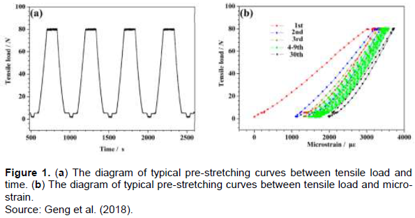
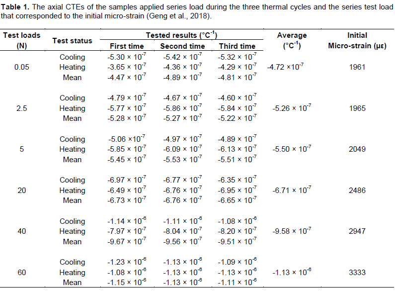
“The time history curve of the tensile load during pre-stretching is as shown in Figure 1a. Figure 1b illustrates the relationship between the tensile load and the micro-strain during pre-stretching. Figure 1b shows that the micro-strain curve exhibited a hysteresis loop that was a typical dynamic viscoelasticity, resulting in strain relaxation. In the initial stage of pre-stretching, the micro-strain of the CFBs showed a significant change, which was an obvious strain relaxation characteristic. The micro-strains of the CFBs decreased and tended toward stability as the pre stretching durations increased. The initial micro-strain values, under the various load conditions, are provided in Table 1” (Geng et al., 2018).
Measurement of coefficients of thermal expansion
“The measurements were performed with a TMA (The schematic diagram and the picture of the test facility for the measurement of coefficients of thermal expansion are as shown in Figure 2) in a pure argon atmosphere. This was chosen based on the inductive dilatometer principle; see investigation reference GJB332A-2004(test method for linear expansion coefficient of solid materials). The argon gas flux was accurately controlled with a mass flow controller. This measurement technique used a linear variable differential transformer (LVDT) (Beijing Wavespectrum Science and Technology Co., Ltd., Beijing, China) where a quartz crystal was attached to a quartz tube that formed a section of the LVDT core. The thermal cycle was the sequence from ambient temperature, heated by an infrared lamp up to 150°C, cooled with liquid nitrogen down to -150°C, and then allowed to return to room temperature” (Geng et al., 2018).
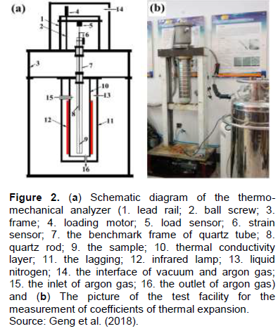
“The controlled rate of heating (or cooling) of the specimen was about 3 to 5°C min-1. The specimen was then placed in a quartz tube frame. The top end of the specimen was fixed with the frame and the opposite end was fixed with a quartz rod that formed a section of the LVDT that was attached to measure the expansion. A software program (This software is developed by Harbin Institute of Technology, Harbin, China) controlled the test parameters and the temperature was continually measured along with the strain data during the heating and the cooling cycles. The CTE was obtained from the linear fit of the data over the entire test-temperature range” (Geng et al., 2018).
“The thermomechanical load induced deformation of the CFBs, which consisted of a reversible and an irreversible component. The reversible component was directly related to the coefficient of the carbon fiber thermal expansion. The irreversible deformation was associated with the changes in the microstructure, which resulted in the creep deformation. The negative CTE was a mixed creep deformation interwoven together with the materials, during the thermomechanical test. The cooling cycle tended to increase the measured deformation. The heating cycle tended to decrease the measured deformation. The mean values were calculated by averaging the values of the slopes that corresponded to the heating and the cooling cycles. This procedure could reduce and compensate for the creep deformation induced error. The expansion coefficient of the cooling stage and the heating stage were measured. The mean values for both were used as the thermal expansion coefficient of the sample” (Geng et al., 2018).
PROBLEM FORMULATION
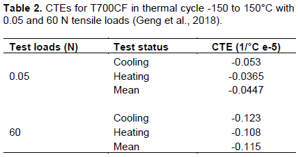
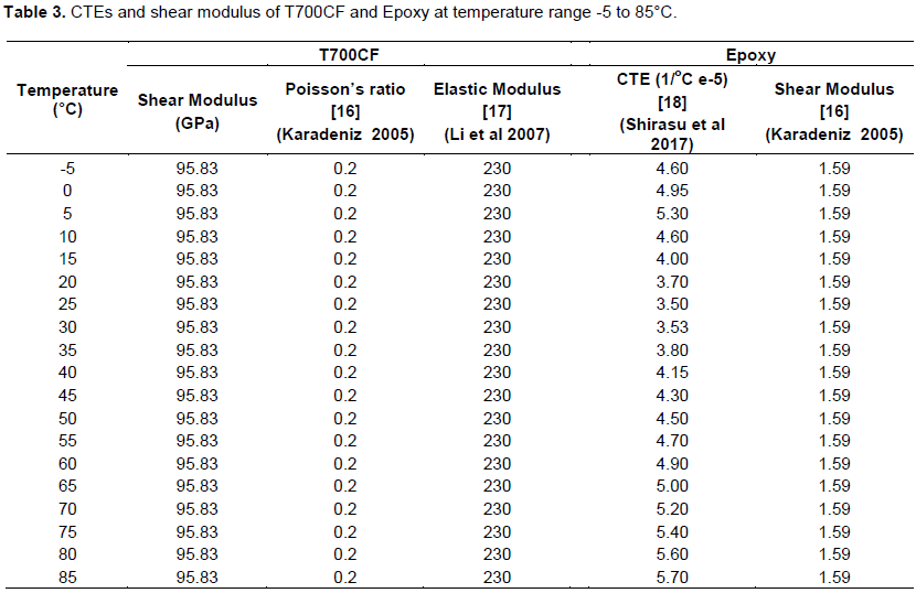
Table 2 (Geng et al., 2018) shows CTEs for T700CF in thermal cycle condition with the presence of tensile load. This condition is similar to the condition of thermal cycles with the presence of MDI because it also imposes tensile load to the structure due to stretching of the space structure wall which is contained with T700CFEC. As it is indicated in Table 2, by increasing the tensile load with the presence of thermal cycles from -150 to 150°C, the CTEs in T700CF decrease. Because the stress free temperature in T700CFEC is assumed to be equal to 23°C (Park et al., 2012) in Table 2, temperatures higher than that are assumed to be heating temperatures and temperatures lower than that are assumed to be cooling temperatures.
In order to perform thermal analysis for T700CFEC with increasing tensile load, Equation 1 can be employed. In a condition of MDI which it seems to be similar to the condition of increasing tensile load on the structure’s wall, CTE of T700CF decreases. In Equation 1, if in this condition shear modulus (G), temperature variation (ΔT), and CTE for epoxy remain constant, by decreasing the CTE for T700CF, ILSs increases. It is important to notice that here decreasing the CTEs for T700CF means having larger negative values. This condition can be analyzed easier with writing Equation 1 in the form of Equation 2.
ILSs = (αepoxy – αcarbon fiber).ΔT.Gmax. (2)
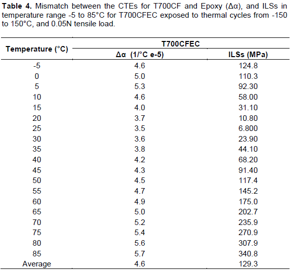
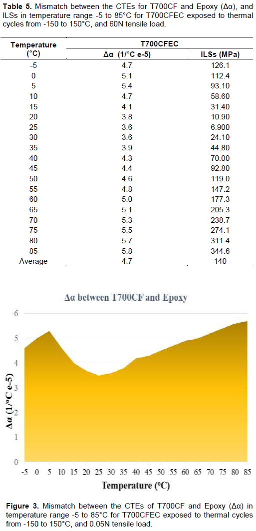
In Equation 2, instead of Δα, αepoxy - αcarbon fiber is substituted. From the results of this thermal analysis it can be inferred that in thermal cycles’ condition with the presence of MDI, ILSs in T700CFEC will increase. With the increase of ILSs, stress concentration at interface areas of carbon fiber and epoxy will increase. This increase in stress concentration may cause increase in the probability for crack initiation and propagation at matrix/fiber interface. Crack propagation in unidirectional composite interface areas may result in de-bonding between carbon fiber and epoxy. In Table 3, shear modulus and CTEs of T700CF and Epoxy are indicated.
RESULTS AND DISCUSSION
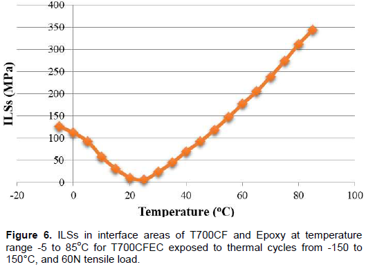
As it is indicated in Tables 4 and 5 and shown in Figures 3, 4, 5, and 6, by increasing tensile load from 0.05 to 60 N in the presence of thermal cycle imposed on T700CFEC, the maximum mismatch of CTEs between T700CF and epoxy is increased by 1.8%. Furthermore, the average mismatch of CTEs is increased by 2.2%. Additionally, ILSsmean and ILSsmax are also increased by 8.3 and 1.1%, respectively, with the increasing of tensile load in the presence of thermal cycle.
For performing a microstructural analysis, it is necessary to understand the behavior of T700CF and epoxy in the presence of thermal cycles and impact. In general, the CTE of T700CF is negative, while the CTE of epoxy is positive. It means that while the T700CFEC is heating, T700CF is contracting due to its negative CTE,
The results have shown that in the state that epoxy’s CTE remain constant, it seems that stress concentration will increase in fiber-epoxy interface area in the presence of thermal cycles with MDI due to imposing tensile load on the structure. This stress concentration can result in crack initiation, propagation, and de-bonding between the fibers and matrix. It is significant to note that according to the experiment (Geng et al., 2018), the load increase in the presence of thermal cycles is only from 0.05 to 60 N. Thus, in many cases, the tensile load imposed to wall’s space structure due to MDI might be less or more than 60 N. Hence, further experimental results are required to estimate the impact effect on thermal fatigue life in status with different tensile loads’ quantities. Nevertheless, it appears that increasing tensile load on T700CF in the presence of thermal cycles will result in decrease of fatigue life. Diminishing thermal fatigue life is due to the increase in ILSs and CTEs’ difference in T700CFEC interfaces areas.
while the epoxy is expanding due to its positive CTE, and while the T700CFEC is cooling, the situation is vise versa. Because in T700CFEC, T700CF and epoxy are bonded, in their interface areas due to the opposite behavior between T700CF and epoxy in cooling and heating conditions, ILSs can develop which may result in crack initiation and/or propagation in micro-size level. Based on Equation 2, with the presence of higher tensile load, ILSs can increase due to the further mismatch between the T700CF’s CTE and epoxy’s CTE which can result in higher crack propagation and decrease in the thermal fatigue life of T700CFEC.
CONCLUSIONS
In the present study, by using experimental results and applying analytical method with Equation 1, the effect of MDI with the presence of thermal cycles on thermal fatigue life of unidirectional T700CFEC is investigated. The results have shown that in this environmental condition in space, the mismatch of CTEs between carbon fiber and epoxy at interface areas might increase. The increase in CTEs’ mismatch and ILSs may result in increase of stress concentration in carbon fibers/epoxy interfaces areas. The stress concentration can cause the crack initiation and/or propagation and de-bonding between carbon fiber and epoxy due to the increment of plastic zone at the crack tip. Consequently, it may cause decrease in thermal fatigue life of the composite.
According to the results obtained in this research, the impact of debris and/or meteorites to T700CFEC in the presence of thermal cycles can increase the ILSs between the fiber and epoxy which can result in crack propagation and fracture. Therefore, it may decrease the T700CFEC thermal fatigue life. This result is of high significance for the safety of future space missions.
RECOMMENDATIONS
It is recommended to perform thermal cycles experiments with the presence of different tensile loads higher than 60 N on carbon fiber to measure its thermal and mechanical properties especially CTEs, within and after the experiment. These results can contribute to estimate the thermal fatigue life of carbon fiber/epoxy composite in the presence of thermal cycles and MDI.
CONFLICT OF INTERESTS
The authors have not declared any conflict of interests.
REFERENCES
|
Adibnazari S and Anvari A (2017). Journal of Mechanical Engineering Research 9(4):34-45. |
|
|
Alijani S and Anvari A (2018). Cycle numbers to failure for magnesium and its alloys in human body fluid. Journal of Chemical Engineering and Materials Science 9(1):1-8. |
|
|
Anvari A (2014). Fatigue life prediction of unidirectional carbon fiber/epoxy composite in Earth orbit. International Journal of Applied Mathematics and Mechanics 10(5):58-85. |
|
|
Anvari A (2016). Friction coefficient variation with sliding velocity in copper with copper contact. Periodica Polytechnica Mechanical Engineering 60(3):137-141. |
|
|
Anvari A (2018). Thermal Life of Carbon Structures: From the Earth to after the Titan. International Journal of Aerospace Engineering Research Article (6 pages), Article ID 7628614, Volume 2018: 1-6. |
|
|
Camargo PHC, Satyanarayana KG, Wypych F (2009). Nanocomposites: Synthesis, Structure, Properties and New Application Opportunities. Materials Research 12(1):1-39. |
|
|
Fitzer E, Gkogkidis A, Heine M (1984). Carbon fibres and their composites (A Review). High Temperatures-High Pressures 16:363-392 |
|
|
Geng G, Ma X, Geng H, Wu Y (2018). Effect of Load on the Thermal Expansion Behavior of T700 Carbon Fiber Bundles. Polymers 10(152):1-14. |
|
|
Hussain F, Hojjati M, Okamoto M, Gorga RE (2006). Review article: Polymer-matrix Nanocomposites, Processing, Manufacturing, and Application: An Overview. Journal of COMPOSITE MATERIALS 40 (17):1511-1575. |
|
|
Karadeniz ZH (2005). A numerical study on the thermal expansion coefficient of fiber reinforced composite materials. Thesis, Graduate school of natural and applied sciences, Dokuz Eylul University, Izmir. |
|
|
Li B, Zhang CR, Cao F, Wang SQ, Chen B, Li JS (2007). Effects of fiber surface treatments on mechanical properties of T700 carbon fiber reinforced BN-Si3N4 composites. Materials Science and Engineering A 471:169-173. |
|
|
Okpala CC (2013). Nanocomposites – An Overview. International Journal of Engineering Research and Development 8(11):17-23. |
|
|
Park SY, Choi HS, Choi, WJ, Kwon H (2012). Effect of vacuum thermal cyclic exposures on unidirectional carbon fiber/epoxy composites for low earth orbit space applications. Composites: Part B. 43:726-738. |
|
|
Petersson H, Motte D, Bjarnemo (2013). Carbon Fiber Composite Materials in Modern Day Automotive Production Lines – A Case Study. Proceedings of the ASME 2013 International Mechanical Engineering Congress & Exposition IMECE2013 November 15-21, San Diego, California, USA. |
|
|
Shirasu K, Nakamura A, Yamamoto G, Ogasawara T, Shimamura Y, Inoue Y, Hashida T (2017). Potential use of CNTs for production of zero thermal expansion coefficient composite materials: An experimental evaluation of axial thermal expansion coefficient of CNTs using a combination of thermal expansion and uniaxial tensile tests. Composites: Part A 95:152-160. |
|
|
Tamilarasana U, Karunamoorthyb L, Palanikumarc K (2015). Mechanical Properties Evaluation of the Carbon Fibre Reinforced Aluminium Sandwich Composites. Materials Research 18(5): 1029-1037. |
|
|
Tyagi M and Tyagi D (2014). Polymer Nanocomposites and their Applications in Electronics Industry. International Journal of Electronic and Electrical Engineering 7(6):603-608. |
|
|
Wu SC, Xu ZW, Kang GZ, He WF (2018). Probabilistic fatigue assessment for high-speed railway axles due to foreign object damages. International Journal of Fatigue 117: 90-100. |
|
Copyright © 2024 Author(s) retain the copyright of this article.
This article is published under the terms of the Creative Commons Attribution License 4.0


