ABSTRACT
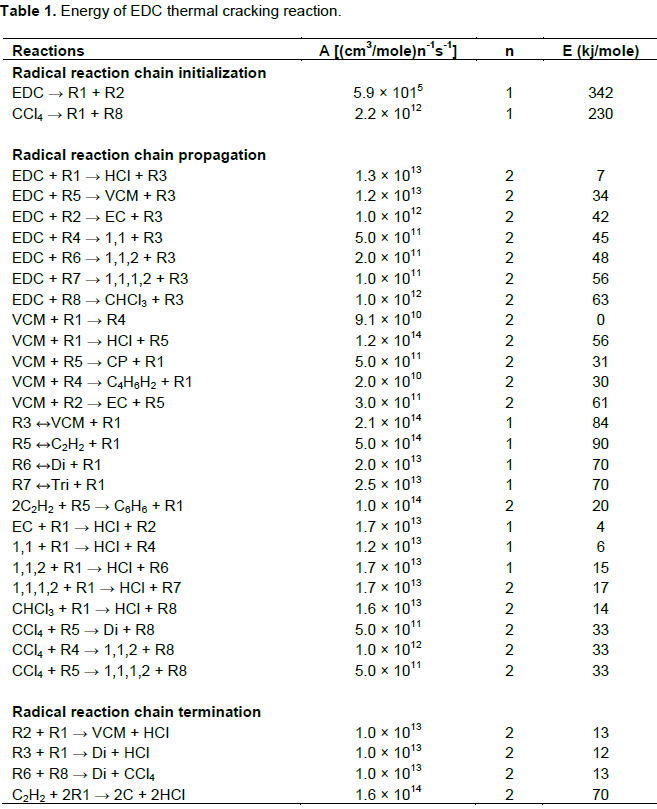
Nowadays, polyvinyl chloride (PVC) is the most usual plastic. Therefore, to make PVC, its monomer called vinyl chloride (VCM) must be produced first. It is a severely endothermic reaction that is done in an ethylene dichloride thermal cracking reactor within a temperature range of 680 to 758°K and pressure range of 2500000 Pascal. Thus, this cracking reaction changes into hydrochloric acid and VCM. In production unit, monomeric chloride has the main and principal role as the core of the process of thermal cracking that occurs in the furnace. Increased wall temperature causes boil gas mixture and pyrolysis reactions. Regarding simulation, the results showed that the number of pyrolysis produced composition with maximum concentration in the length of the reactor. This illustrated that these compositions participated in secondary reactions. Furthermore, by increasing the amount of coil outlet temperatures, the amount of formed coke will increase. If carbon tetrachloride is considered as the chlorine radicals, it has an important role as the motivator in the cracking procedures, radicals causing an enhancement in VCM production.
Key words: Carbon tetrachloride, conversion factor, coke, coil outlet temperatures, thermal cracking.
Designing and simulation of thermal cracking reactor of the chemical reactions in the processes and heat transfer in the furnace are very complex. Therefore, this process from the chemical reactions engineering perspective and from the perspective of transfer phenomena is highly regarded. Computational Fluid Dynamics (CFD) tools help us to investigate the development of detailed models of these reactors, and by understanding the basic principles, the optimized design of reactor, saving of cost and time performance of this equipment in a virtual laboratory can be done. In this research, the author investigates the proposed model of 1,2-dichloroethane (EDC) cracking process in an industrial furnace and by operational data from a petrochemical unit, qualifies the model and removes its reductions. To begin, previous research done on this specific subject was studied. Moreover, the reactor mathematical models were provided and solved by numerical software. Thereby, the operation of the reactor at different operating conditions was investigated as well as sensitivity analysis of effective parameters. As a result, new reactors or increasing the optimization capacity of existing reactors can be designed.
Molecular cracking
Molecular cracking is a process that is used in the petrochemical industry and is used to reduce their hydrocarbons molecular weight by breaking their bonds. This process is the main principal of converting crude oil to useful fuels such as gasoline, diesel, jet fuel and kerosene. Thermal cracking, catalyst cracking, hydrocracking and cracking by water vapour are the most useful cracking processes in the industry. This process is either done with high temperature and pressure without a catalyzer or with low temperature and pressure with a catalyzer.
Geometry of thermal cracking reactor
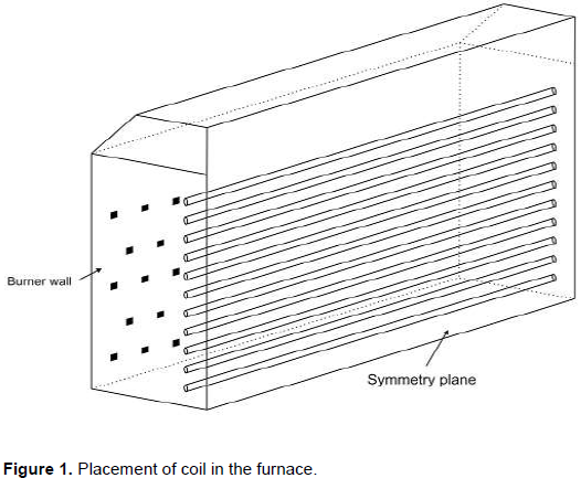
In EDC thermal cracking process, coils containing process fluid in a box called furnace, are positioned horizontally. Coils placed inside the furnace are shown in
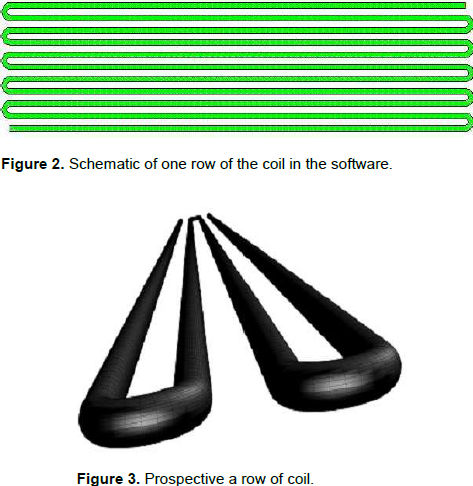
Figure 1 (Kaggerud , 2007). They are positioned on both sides of the furnace wall. By burning the gases of these furnaces heat is produced and then transferred to the coils by convection or radiation. The number of intended coils to simulate 11 rows of pipes (Inconel 600) with overall length of 95 m and length of each row tube is 13.5 m. The inner diameter of coils is 0.134 m and the distance between the centers of the two tubes is 0.32 m. Schematic of one row of the coil in the software is in Figure 2. Furthermore, prospective a row of coil was shown in Figure 3.
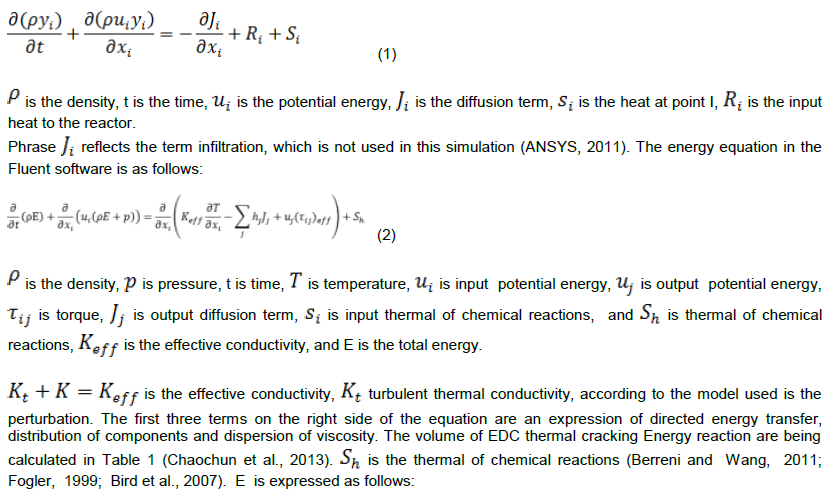
Mass balance equation in the software is proposed in form of Equation.1


Standard k-ε model
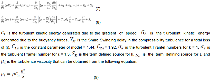
This is a comprehensive model that accounts for the simplest turbulence model. Two educational turbulent models enable solving of the two transfer equations that separately determine turbulent length and time scale. Standard k-ε model is useful for powerful engineering calculations. The power of this equation, its economical and acceptable accuracy for a wide range of turbulent flow is as a result of its popularity in industrial flow and heat transfer simulation. This model is a semi-empirical model. Standard k-ε model is a model based on transfer equations for kinetic turbulent energy and dissipation rate (ε). In achieving the standard k-ε model it is assumed that the fully turbulent flow and molecular viscosity effects are ignored. Because of the strengths and weaknesses of the equation to improve its performance, k-ε realizable and k-ε RNG model were introduced. K and ε are obtained by solving simultaneously the following two equations:
RNG k-ε model
This model is based on statistical methods. This model is the same as the standard k-ε model, but with the following modifications:
(1) An additional term (ε) that significantly increases accuracy for flow to layer velocity.
(2) The effect of the rotational movement (vortex motion) included turbulences and increases accuracy for rotary flow.
(3) An analytical formula for turbulent Prantel numbers is provided, as standard k-ε model is considered a fixed amount
(4) While the standard k-ε model is the model for high Reynolds numbers, the theory of RNG for analysis of a differential equation for the turbulent viscosity can be provided considering the effects of low Reynolds. Effective use of this feature depends on proper behavior of the region near the wall of the furnace.
K-ε realizable model
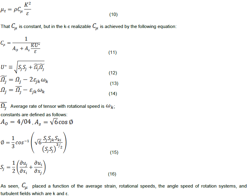
This model has limitations on Reynolds stresses that match with the physics of turbulent flows. This is possibly not in the standard k-ε model and not in the k-ε RNG model; but in places with a large curvature in flow lines, vortex and rotation of the screw. K-ε RNG and k-ε realizable models have significant progress towards standard k-ε model. Preliminary studies show that the k-ε realizable model between k-ε models has best performance for confirmation numbers of complex flows and segregated flows. In all of these cases, the performance of this model is better than the standard k-ε model. As it was observed that in the standard k-ε model, turbulent viscosity achieved the following equation:
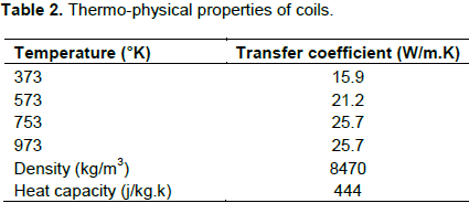
Thermo-physical properties of coils are being illustrated in Table 2.
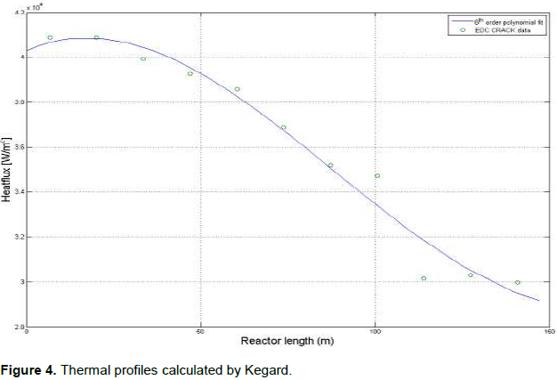
The profile of heat is applied in the walls. A total of eleven walls were located and each row of coil has a heat profile of its own. The thermal flux resulting from furnaces applied on the coils level used for proposed profiles was provided by Kegard (2007). The length of each row of coils can be categorized as profile provided by the amount of heat to be entered in the software (figure 4).
METHODOLOGY OF THE WORK (SIMULATION)
Boundary conditions of cracking reactor
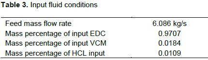
Inlet flow
Input for fluid flow based on mass flow rate and percentage of each of the compounds at the entrance of the inlet is used for the mass flow condition that accounts for the boundary condition (Table 3).
Output flow
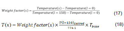
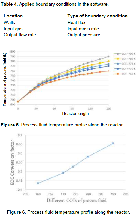
The output flow is used for pressure boundary condition. The boundary conditions are summarized in Table 4. The conversion factor and amount of coke formed are based on different COTs.In this part of the research, the different COTs EDC conversion factor and the amount of formed coke are investigated. The amounts of COT based on recent issues in review of EDC cracking processes with values ​​of 760, 770, 780 and 790 are selected. To achieve this profile, it is first calculated

and by using the proportion, a variable factor is described. As a result, the new temperature profile in a particular COT from the new data was achieved. In this method, input temperature of the coil does not change and base COT temperature multiplies in the
; the other base profile in Equations 17 and 18 multiplies in a constant parameter to obtain new profile points.

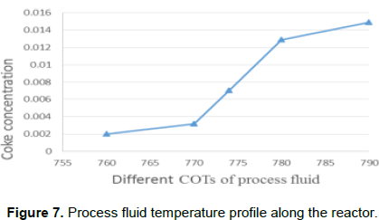
The results of these calculations can be seen in Figure 5. COT different temperature profiles were obtained. Figure 6 indicates the EDC conversion factor in different COTs; higher conversion factor will be higher in the COTs. In Figure 7, if the amount of COT is higher, the amount of formed coke also will be higher. So by regarding the simulation results, it can be said that for optimum economic performance of furnace, the temperature profile of the fluid is very important.
INVESTIGATING ADDING CARBON TETRACHLORIDE AS PROPULSION
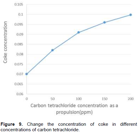
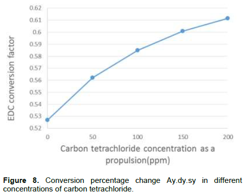
By adding this compound to the feed in addition to increased conversion factor, it has other effects on the process. Due to increasing number of chlorine radicals in the process, the number of unwanted compounds and acetylene production, coke production increased. Creating unwanted compounds in the next stages, in addition to VCM treating problem leads to an important loss. As shown in Figure 8, conversion factor increases with increasing carbon tetrachloride; on the other hand, in Figure 9, coke is formed with increase in carbon tetrachloride. Regarding simulation results, it can be said that for optimum economic performance of furnace, the temperature profile of the fluid is very important.
Therefore, by optimizing the amount of carbon tetrachloride added to the feed for economic performance of thermal cracking unit is very important. In this amount of propulsion conversion factor increases as an allowable limit and reactor performance for forming coke and unwanted compounds are economical (Figure 5).

K-ε realizable model is the most appropriate model for calculation because of the following reasons (Berreni and Wang, 2011):
(2) A modified transferring equation for scattering rate, ε, can be considered. Therefore, this model is an exact equation for fluctuations transfer.In this research, the effect of adding carbon tetrachloride as a propulsion has been investigated. According to the result of this research and other issues, if the amount of this compound is not more than 100 ppm, conversion factor will be increased; if this amount is more than 100 ppm, it is not suggested economically.
The authors have not declared any conflict of interests.
REFERENCES
|
Kaggerud TH (2007). Modeling an EDC Cracker using Computational Fluid Dynamics (CFD), Norwegian University of Science and Technology. P 70.
|
|
|
|
Li C, Hu G, Zhong W, He W, Du W, Qian F (2013). Coke Deposition Influence Based on a Run Length Simulation of a 1,2-Dichloroethane Cracker". Ind. Eng. Chem. Res. 49:17501-17516.
Crossref
|
|
|
|
ANSYS I (2011). ANSYS FLUENT User's Guide.
|
|
|
|
Berreni M, Wang M (2011). Modelling and dynamic optimisation for optimal operation of industrial tubular reactor for propane cracking in Computer Aided Chemical Engineering. 29 Pistikopoulos MCGEN, Kokossis AC, Eds., ed: Elsevier. pp. 955-959.
|
|
|
|
Fogler S (1999). Element of chemical reaction engineering.
|
|
|
|
Bird RB, Stewart WE, Lightfoot EN. Transport Phenomena: Wiley, 2007.
|
|
|
|
Berreni M, Wang M (2011). Modelling and dynamic optimization of thermal cracking of propane for ethylene manufacturing", Comput. Chem. Eng. 12:2876-2885.
Crossref
|


 and by using the proportion, a variable factor is described. As a result, the new temperature profile in a particular COT from the new data was achieved. In this method, input temperature of the coil does not change and base COT temperature multiplies in the