Review

ABSTRACT
In this paper, a hexagonal fractal antenna is proposed for wireless applications. The basic shape of the fractal antenna is a hexagon which is modified by inserting smaller hexagons along the periphery of the generator structure. The proposed antenna exhibits a bandwidth of 7.5 GHz in the frequency range of 3.3-10.8 GHz. The band notch for WLAN rejection at 5.75 GHz is obtained by etching hair-pin slot in the feed structure of the antenna. The fractional bandwidth of the antenna is 53.33 and 55.62% and the VSWR obtained at the notch frequency of 5.75 GHz is 5.2 which are highly suitable for wireless communication.
Key words: Fractal antenna, Ultra wide-band (UWB), VSWR, notch, hair-pin slot.
INTRODUCTION
In recent years, wireless communication systems have encouraged the need for ultra wide band antennas making it compatible to different wireless applications. The FCC has allocated high data rate and short range wireless unlicensed band spectrum from 3.1 to 10.6 GHz for Ultra wide-band (UWB) system. The UWB system requires small size, high data transmission, low power consumption, higher bandwidth, simple hardware and omni-directional radiation pattern for its transmission (Federal Communication Commission, Schantz, 2005; Kumar and Ray, 2003). The enormous bandwidth of UWB system contains various preexisting narrow band spectrums that potentially cause interference to the whole UWB system.
The UWB system brings miniaturization concept in antennas to satisfy different needs for continuous, convenient and compact access of updated information. The miniature concept introduces a word ‘fractal’ to the UWB system which possess various Koch, Sierpinski-carpet, minkowski, cantor, square, triangular geometries (Ryu and Kishk, 2009; Mishra et al., 2011; Chaouche et al., 2018; Sharma and Bhatia, 2019; Harkanche et al., 2018; Bukkawar and Ahmed, 2018; Kim and Park, 2006; Liu et al., 2010; Pharwaha et al., 2018; Wu et al., 2010; Xiao et al., 2014; Liu et al., 2010; Sreerag and Sudha, 2014; Zou and Jiang, 2020; Zhou et al., 2008). The original concept of fractal came from the in-depth study of patterns of nature. Even these complex geometries have been shown in galaxies, cloud boundaries, mountain ranges, coastlines, snowflakes, trees, leaves, ferns and much more. The fractal concept has been employed more in antenna design in place of Euclidean geometries. These fractals are made by introducing non-integer factors to their respective dimensions. These structures are well known for their self-similarity and space filing properties which have strong impact on frequency bandwidth of the antenna (Kumar and Ray, 2003). Fractals have sharp edges and corners that make abrupt changes in the direction of current and enhance the radiation characteristics of the antenna. Therefore, fractals are efficient radiators of electromagnetic radiations.
Recently, UWB antenna system has been reported as non-planar system just because of their protruded structures which cannot be integrated with integrated circuits (Ryu and Kishk, 2009; Mishra et al., 2011; Chaouche et al., 2018; Sharma and Bhatia, 2019; Harkanche et al., 2018; Bukkawar and Ahmed, 2018). The UWB antenna system also contains various narrow band spectrums that may generate interference between these spectrums. These spectrums include IEEE 802.11a and HIPERLAN/2 operating in 5.15 to 5.825 GHz. This interference can be overcome by introducing different notch structures in antenna design (Kim and Park, 2006). Notch functions are highly desirable to mitigate interference between UWB and narrow band spectrum. To avoid interference, different design methods have been proposed earlier like cutting of slots on the patches (Kim and Park, 2006; Liu et al., 2010; Pharwaha et al., 2018; Wu et al., 2010; Xiao et al., 2014) or quarter wavelength tuning stubs within the slots on the patch (Liu et al., 2010), etching different compact co-planar structures (Sreerag and Sudha, 2014; Zou and Jiang, 2020), using fractal slots and parasitic elements (Ryu and Kishk, 2009; Zhou et al., 2008). However, most of these designs are very complicated as they lead to increase in fabrication costs and difficult to integrate with microwave integrated circuits.
In this paper, hexagonal fractal antenna (HFA) for UWB applications with band notch characteristics is presented. The proposed antenna covers a frequency bandwidth of 7.5 GHz (3.3 - 10.8 GHz) for UWB system. The band notch at 5.75 GHz (5.12 - 5.9 GHz) is provided by etching hair pin slot in the feed structure of the proposed antenna.
DESIGN OF PROPOSED ANTENNA
The configuration of the proposed antenna labeled with design parameters is shown in Figure 1 and various hexagonal fractal iterations are shown in Figure 2. A monopole comprises of a hexagonal radiator to which twelve small hexagonal units are added to increase the electrical length of the hexagonal units add extra sharp edges and corners to the design so that there will be an abrupt change in direction of current which provides better efficient antenna system and enhance the radiation characteristics. An additional hexagonal iteration has been introduced to achieve higher frequency bandwidth. The hexagonal radiator at the top layer and modified elliptical ground plane at the bottom layer are printed on a 1.6 mm thick FR4 substrate with relative permittivity of 4.4. The dimensions of antenna and the modified elliptical ground plane are shown in Table 1. The dimensions of basic hexagon geometry are calculated by equating its area with cylinder of radius r (given by  side of hexagon ‘b’) and the lower frequency (fL) corresponding to VSWR=2 can be calculated by the Equation 1,

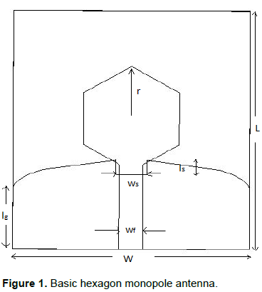
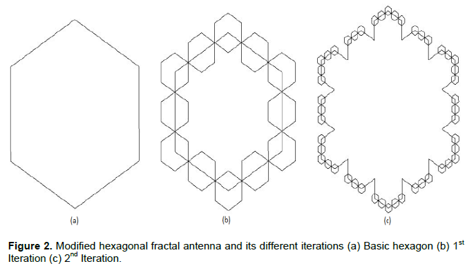
Where ‘l’ is the electrical length, ‘a’ (given by  is the radius of equivalent cylindrical monopole and ‘h’ is the distance between 50 ? feed line and the ground plane. The radius and circumference of equivalent cylindrical monopole are the main factors for modifying the resonant frequency of the antenna. The fractal-like hexagon units are the factor of 1/4 with respect to its basic hexagon geometry. These hexagon fractal units are responsible for increasing the electrical length of the proposed antenna without occupying any additional space within the antenna. Moreover, the ground plane is modified along the width in elliptical manner to increase the return loss at respective frequencies.
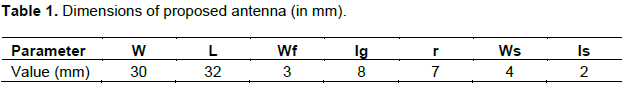
Figure 3 shows the return loss vs frequency plot of the proposed antenna with different iterations. Promising results can be obtained from the second iteration of the antenna as it is well in accordance with the conditions imposed by Federal Communications Commission (FCC). The second iteration covers fully UWB spectrum (3.3 - 10.8 GHz) from achieved bandwidth 3.41 - 12.25 GHz. This is due to the apparent increase in perimeter thereby increasing the electrical path of the current leading to a pronounced frequency bandwidth.
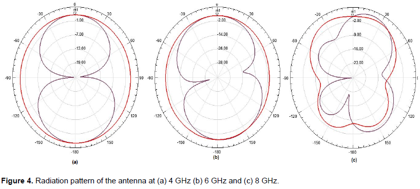
For an antenna to transmit and receive properly, the radiation pattern should be stable at different frequencies within its operating band. This is illustrated in Figure 4 which illustrates the antenna’s radiation characteristics at 4, 6 and 8 GHz, respectively.
ANTENNA WITH HAIR-PIN SLOT
The entire UWB spectrum, that is, 3.3 - 10.5 GHz contains several other narrowband systems like WiMAX (3.4 - 3.6 GHz), WLAN (5.15 - 5.35 GHz, 5.725 - 5.825 GHz), C-band (4-8 GHz) etc. So interference becomes quite imminent between the co-existing UWB system and the narrowband systems. In order to mitigate the interference and depending on the application, certain stop bands can be created so as to reject certain frequencies meant for a particular application. In this paper, emphasis is laid on rejecting the WLAN frequency by introducing a hair-pin slot structure from the feed line. The dimensions of the slot are calculated using the Equation 2
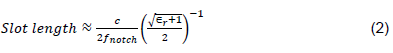
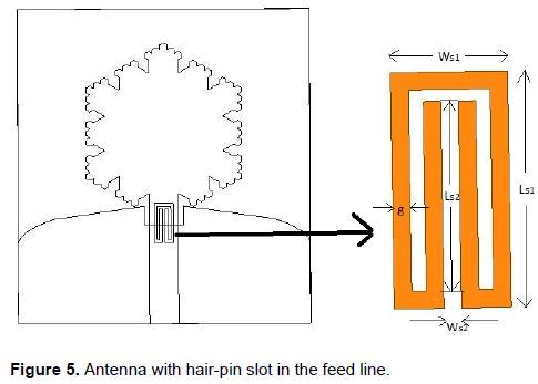
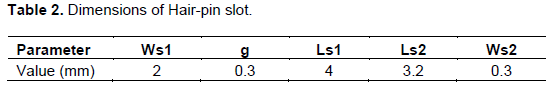
Where fnotch denotes the desired frequency where the notch is to be obtained. The insertion of the notch structure causes current nulls at a certain frequency. This is characterized by a stop band in the S11 plot of the antenna. The antenna with hair-pin slot in the feed line is shown in Figure 5. The detailed dimensions of the hair-pin slot are shown in Table 2.
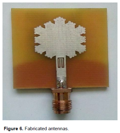
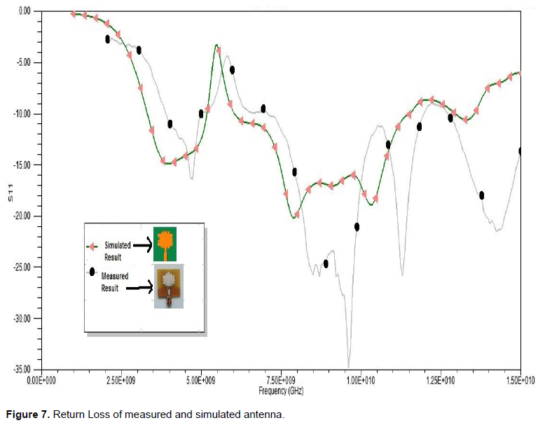
The fabricated antenna with hair-pin slot in the feed is shown in Figure 6. Figure 7 shows the return loss plot of the antenna. The fabricated antenna result is also embedded in order to provide a comparative analysis. The discrepancy between simulated and measured results could be attributed to the loss tangent (tan δ) of the substrate and tolerances in manufacturing. Thus it can serve as a potential UWB antenna.
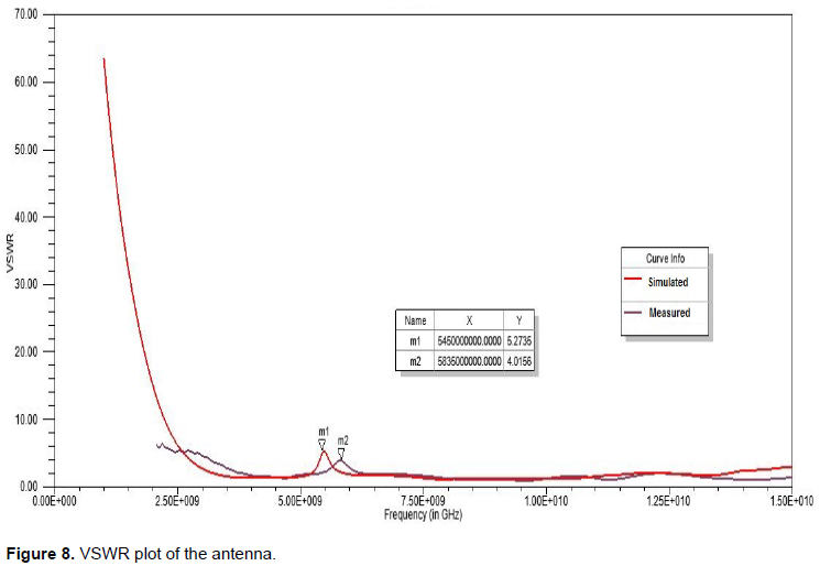
The obtained VSWR of the simulated and measured antenna is shown in Figure 8. The measured VSWR value is 4.01 at 5.4 GHz which implies that approximately 36% power is reflected back from the antenna terminals at this frequency and therefore the antenna would serve as a good candidate for WLAN frequency rejection.
The current density represents the plot and the surface current at different frequencies. Figure 9 denotes the current distribution on the surface of the antenna as well as on the ground plane.
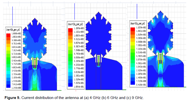
It is observed from the plot that at lower frequencies, current is mainly concentrated on the lower part of the patch as well as on the ground.
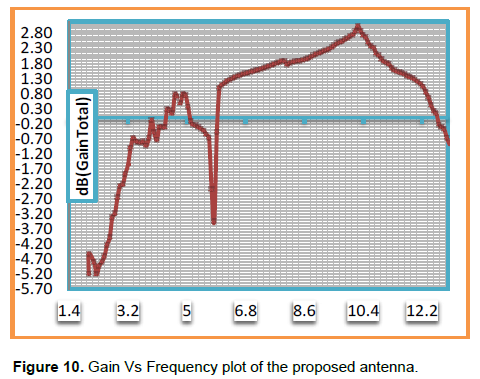
A large density of current is observed on the microstrip feed line near its junction with the patch. The position of the hair-pin slot is created based on this position in order to create a null at the region of highest current concentration. At higher frequencies, the current is evenly distributed throughout the patch as well as on the ground. Thus, increasing the operating frequency results in an increased value of gain. The Gain vs Frequency plot of the antenna is shown in Figure 10.
CONCLUSION
In this paper, a printed monopole antenna for UWB applications is analyzed in details. The antenna exhibits a wide bandwidth of 7.5 GHz and has omni-directional radiation pattern at different frequencies in the UWB range (3.3 - 10.8 GHz). By introducing hair pin slot in the feed line of the antenna, successful band rejection is achieved in the WLAN frequency band (VSWR 5.2 at 5.75 GHz) which is a tangible accomplishment in comparison with other existing methods like Y slot structure (VSWR 3.2) and U slot structure (VSWR 5). The proposed antenna serves as a potential candidate for UWB applications and can be efficiently utilized for high data rate transmission within short distances, medical imaging (especially for detecting breast cancer etc.), spectroscopy etc. In future, more emphasis shall be given in mitigating the mutual coupling between closely placed (less than λ/2) antenna systems.
CONFLICT OF INTERESTS
The authors have not declared any conflict of interests.
REFERENCES
|
Antenna," International Conference on Wireless Communications. Signal Processing and Networking (WiSPNET) pp. 1-4. |
|
|
Chaouche YB, Nedil M, Messaoudene I, Bouttout F (2018). CPW-fed Hexagonal Modified Sierpinski Carpet Fractal Antenna for UWB Applications. 2018 IEEE International Symposium on Antennas and Propagation and USNC/URSI National Radio Science Meeting pp.1045-4046. |
|
|
Federal Communication Commission ,Washington, DC, USA. Federal Communication Commission revision of Part 15 of Commission's rules regarding ultra-wideband transmission systems. First Report and Order FCC.02. V48. |
|
|
Harkanche SB, Nandgaonkar AB, Khobragade SV (2018). Tenuous Hexagonal Microstrip Fractal Antenna for UWB Applications. Proceedings of the Second International Conference on Intelligent Computing and Control Systems (ICICCS), pp. 636-639. |
|
|
Kim KH, Park SO (2006). Analysis of small band-rejected antenna with the parasitic strip for UWB. IEEE Antennas and Wireless Propagation Letter 54(6):1688-1692. |
|
|
Kumar G, Ray KP(2003). Broadband microstrip antennas. Artech House. |
|
|
Kushwah R P S(2005). "Bow-shape single layer with single probe feed microstrip patch antenna," 2005 Asia-Pacific Microwave Conference Proceedings, Suzhou, China 4:1-4. |
|
|
Kushwah R P S, Dubey M, Singhal PK(2006), "Design of a Triple Layer Microstrip Patch Antenna," IEEE International Workshop on Antenna Technology Small Antennas and Novel Metamaterials.White Plains, NY, USA pp. 49-52. |
|
|
Liu HW, Ku CH, Wang TS, Yang CF (2010). Compact monopole antenna with band-notched characteristics for UWB application. IEEE Antennas and Wireless Propagation Letters 9:397-400. |
|
|
Liu HW, Ku CH, Yang CF (2010). Novel CPW-fed planar monopole antenna for WiMAX/WLAN application. IEEE Antennas and Wireless Propagation Letters 9:240-243. |
|
|
Mishra SK, Gupta RK, Vaidya A, Mukherjee J (2011). A Compact Dual-Band Fork-Shaped Monopole Antenna for Bluetooth and UWB Applications. IEEE Antennas and Wireless Propagation Letters 10:627-630. |
|
|
Pharwaha A P S, Kakkar S, Kamal TS (2018). On the Optimal Design of Fractal Tuning Stub UWB Patch Antenna with Band-Notched Function. 8th International Conference on Information Science and Technology pp. 268-273. |
|
|
Ryu KS, Kishk AA (2009). UWB antenna with single or dual band-notched for lower WLAN band and upper WLAN band. IEEE Antennas and Wireless Propagation Letter 57(12):3942-3950. |
|
|
Schantz H (2005). The art and science of ultra wideband antennas. Artech House. |
|
|
Sharma N, Bhatia S S (2019). Performance enhancement of nested hexagonal ring-shaped compact multiband integrated wideband fractal antennas for wireless applications. International Journal of RF and Microwave Computer-Aided Engineering 30(3):1-21. |
|
|
Sreerag M, Sudha T (2014). A Hexagonal Boundary Fractal Antenna with WiMAX Band Rejection. IEEE National Conference on Communication, Signal Processing and Networking (NCCSN). pp. 1-4. |
|
|
Wu SJ, Chen CH, Tang JH (2010). Study of an ultra-wideband monopole antenna with a band-notched open loop resonator. IEEE Antennas and Wireless Propagation Letters 58(6):1890-1897. |
|
|
Xiao Y, Zhong-Yong W, Ji L, Zi-Lun Y, Qun AK (2014). Two-step Beveled UWB Printed Monopole Antenna with Band Notch," International Journal of Antennas and Propagation. |
|
|
Zhou HJ, Sun BH, Liu OZ, Deng JY (2008). Implementation and investigation of U-shaped aperture UWB antenna with dual band-notched characteristics. Electronics Letter 44(24):1387-1388. |
|
|
Zou Q, Jiang S (2020). A compact flexible fractal ultra-wideband antenna with band notch characteristic. Microwave Optical Technology Letter 63(3):1-7. |
|
Copyright © 2024 Author(s) retain the copyright of this article.
This article is published under the terms of the Creative Commons Attribution License 4.0


