Full Length Research Paper
ABSTRACT
This new study on effects of gyroscope demonstrates the action on the spinning disc that the eight interrelated inertial torques system generated by its rotating masses. The physics behind this inertial torques manifest the action of the resistance and precession torques, which physics are described and explained. The latest research on the gyroscopic properties revealed the deactivation of the inertial torques that contradicts the principles of classical mechanics. Practical tests of the blocking of the gyroscope motion around one axis displays the deactivation of inertial torques acting around the axis of the load torque. In this condition, the gyroscope with one side support turns down under the action of its weight and frictional forces produced by the action of the precession torque and weight of the movable components. The precession torque is presented by the change in the angular momentum, while other inertial torques is deactivated. These phenomena present the new unknown gyroscopic effect that needs a deep study and explanation. This work considers the attempt to describe the physics of the deactivation of the gyroscopic inertial torques around two axes and the action of the precession torque in a case of the gyroscope motion around one axis.
Key words: Gyroscope theory, inertial torque, deactivation of inertial torques
INTRODUCTION
Beginning from the eighteen century, gyroscopic problems were studied by famous, outstanding, and ordinary scientists that developed separate mathematical models for the action of inertial torques which manifest gyroscopic effects. However, their analytical approaches could not describe their physics on a full scale. The reason for this fact is that gyroscopic effects should be further described by the terms of the principles of the kinetic and potential energies developed in the middle of the nineteenth century. In-depth studies on gyroscopic effects started in the twentieth century with intensification on the work of machines and mechanisms .
Since then, numerous published articles dedicated to gyroscopic effects contain simplifications, assumptions, and corrections of the mathematical models with the aim to get results that should match with practical tests (Armenise et al., 2010; Deimel, 2003; Greenhill, 2010; Scarborough, 2011). The inertial forces acting on a gyroscope and motions are expressed by wrong analytical models and explanations of the physics of gyroscopic effects (Ferrari, 2006; Weinberg, 2011). For solutions to engineering problems in relation to the rotating objects, the numerical modeling of gyroscopic motions is developed with the software that does not describe the physics of the processes due to the complexity of the forces acting on it (Klein and Sommerfeld 2008; Taylor, 2005; Gregory, 2006; Aardema, 2005). The latest research on gyroscopic effects discovered the action on the running gyroscope of the system of interrelated inertial torques based on the principle of kinetic energy and conservation law (Usubamatov, 2018, 2016.
The mathematical models for the gyroscopic effects with the action of the system of interrelated inertial torques well-matches practical results. Nevertheless, deactivation of the inertial torques in a case that involves blocking of the gyroscope motion around one axis is not well described and explained (Usubamatov, 2015, 2018). The phenomena of the deactivation of inertial forces contradict the principle of physics hence the matched results of analytical and practical approaches do not guarantee their full proof (Peters, 2001; Taylor, 1996; Engineering ToolBox, 2004). This work represents the result of the solution for the motion of the gyroscope around one axis, explains the physics of the deactivation of the inertial torques, and the action of the precession torque on the gyroscope. Nevertheless, the proposed solution and conclusion cannot be accepted as the final truth; so researchers can present their own vision for the deactivation of gyroscopic inertial forcers.
METHODOLOGY
The mathematical model for the gyroscopic motions around one axis and use of the test stand with the technical parameters of the Super Precision Gyroscope “Brightfusion LTD” and conditions are presented in the published manuscript (Usubamatov 2018). The equations of the inertial torques Ti generated by the rotating masses of the spinning disc [11] are presented in the following expression:
Ti = DiJωωx (1)
Where Di is the factor that depends on the type of inertial torque, that is, generated by the centrifugal, common inertial, Coriolis and the change in the angular momentum; J is the mass moment of inertia of the spinning disc; ω is the angular velocity of the disc; ωx is the angular velocity of the disc’s precession.
Expression of the inertial torques (Equation 1) is used for the mathematical model of gyroscope motion around one axis in which the Euler’s differential equation is presented by the following expression (Usubamatov, 2018)
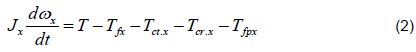
where ωx is the angular velocity of the gyroscope around axes ox; Jx is the mass moment of inertia of the rotating components of the stand; T is the resulting torque generated by the weight of the gyroscope components, Tct.x, Tcr.x, are inertial torques generated by the centrifugal, Coriolis forces acting around axis ox; Tfx = TfA + Tfm is the frictional torques acting on gyroscope’s supports; TfA is the frictional torque generated by the weight of the gyroscope components and acting on the supports; Tfm is the frictional torque acting on the supports generated by the centrifugal forces of the centre of mass; Tfpx = Tfin.y + Tfam.y is the frictional torque generated by the precession torques acting around axis oy.
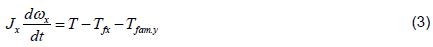
Practical tests of the gyroscope motion around one axis demonstrate its fast motion from upper location to down. It means the inertial torques generated by the rotating mass elements Tct.x, Tcr.x. Tin.y do not act but should act on the inertial torque generated by the center of mass. This statement is a logical solution that was validated by the test. Thereafter, Equation 2 is presented by the following expression:
The load torque T around axis ox is generated by the weight of gyroscope components and represented by the following expression:

where M is the gyroscope mass; s is the axle mass; G is the mass of the counter-weight; g is the gravity acceleration; l is the distance of location of the gyroscope’s centre of mass; a is the axle length and the distance of location of the counter-weight’s center of mass; γ is the axle inclination angle, mr is resulting load mass, lm is location of resulting load mass (Usubamatov, 2018).
Frictional torques generated by the weight of the gyroscope components and acting on the supports is represented by the following equations:

where b is the mass of the centre beam; f is the frictional coefficient of supports; d is the diameter of the supports; δ = 45° is the angle of the beveled sliding bearing; l is the distance from the axis oy to the centre mass of the spinning rotor; g is the gravity acceleration; and other parameters are as specified above.
The angular velocities of the gyroscope around axes generate the centrifugal forces produced by the resulting centre of mass and hence the frictional torque acting on the supports that is expressed by the following equation:
where mr is the resulting centre of mass; lm is the distance of the location of the resulting centre of mass; all parameters are as specified above.
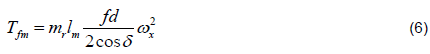
The precession torque causes additional load on the supports thereby increasing the value of the frictional force of the supports. Hence, the frictional torques generated by the precession torques is represented by the following equation:
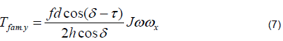
where h, τ, δ are the constructional parameters of the gyroscope’s stand, J is the mass moment of inertia of the spinning rotor, ω is the angular velocity of the spinning rotor, and other parameters are as specified above.
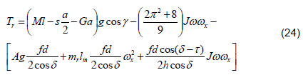
The modified equation for the gyroscope motion (Usubamatov, 2018) is represented by the following:
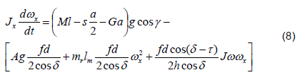
where all parameters are as specified above (Usubamatov, 2018).
Case study and practical tests
Substituting the gyroscope stand data (Usubamatov, 2018) and the coefficient of friction f = 0.16 into Equation 8 gives the following expression:
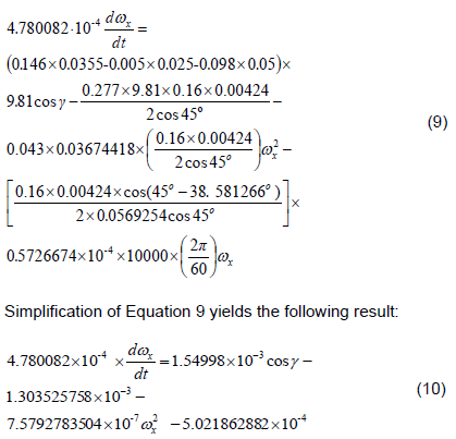
The right component (7.5792783504×10⁻⁷  ) of Equation 10 has the small value of high order that can be neglected. Following the steps of computing are the same as represented in the cases studied (Usubamatov, 2018) and all comments are omitted.
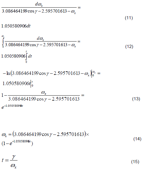
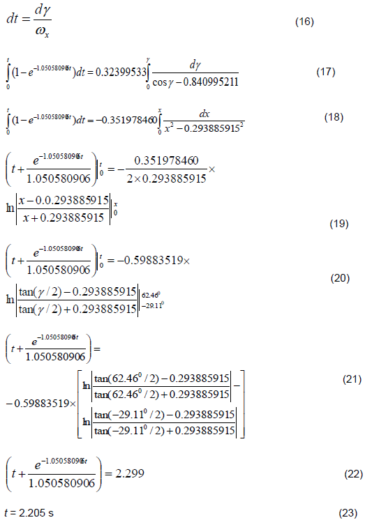
From the above, the obtained result is less than the time computed when the combined precession torque acts on the condition (Usubamatov, 2018) (t = 2.205 s) < (t = 2.24 s) and closer to the time of the tests (t = 2.10 s). This implies that the free turn of the running gyroscope generates only the precession torque of the change in angular momentum.
RESULTS AND DISCUSSION
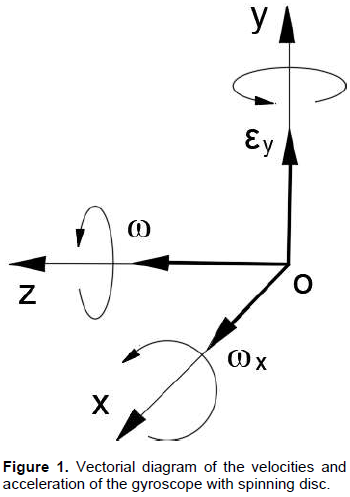
The inertial torques acting on the spinning disc (Equation 1) contains two variable components ω and ωx in which the product ωωx = εy represents the acceleration around axis oy. The angular velocity of the spinning disc ω around axis oz is accepted as constant and does not change the value. The precession angular velocity of the gyroscope ωx around axis ox is variable. The running gyroscope under the action of the external torque rotates around three axes ox, oy, and oz. These motions express the work of the potential energy of the gyroscope weight and kinetic energy of the spinning disc along axes of motions. The kinetic energy of the spinning disc is expressed by the action of the change in the angular momentum around axis oz and by the action of the inertial torques generated by the centrifugal, common inertial, and Coriolis forces around axes ox and oy. The action of all inertial torques around the axes is interrelated. The vectorial diagram of the angular velocities, acceleration of the spinning disc and the gyroscope around axes are presented in Figure. 1. All rotational motions of the gyroscope around axes are in the counter-clockwise directions if considered from the tips of the co-ordinate axes.
The blocking of the running gyroscope from turning around the axis oy causes rotation to stop the acceleration and rotation around this axis, that is, ωωx = εy = 0. Since the angular velocity of the spinning disc ω is constant, the angular velocity of the precession around axis ox is an absence (ωx = 0). This implies that all inertial torques (Equation 1) have the zero values Ti = 0, that is, they are deactivated formally for the accepted condition and should be proven physically. The gyroscope starts to turn down under the action of the gyroscope weight and frictional forces acting on the supports that confirmed the practical tests.
The new condition of the gyroscope motion around axis ox with the high angular velocity should generate the new values of inertial torques and frictional forces generated by the rotating mass of the spinning rotor. However, practice demonstrates their absence, except the action of the precession torque, which is conducted according to the principles of classical mechanics. Other inertial torques generated by the rotating mass elements of the spinning disc are deactivated, and at the first sight, acted in contradiction to the laws of physics.
Analysis of the external and inertial torques acting on a gyroscope yields the following outcomes: The torques acting on the gyroscope and its motions around three axes are results of the work of potential and kinetic energies. The potential energy is expressed by the location of the gyroscope weight. The kinetic energy is expressed by the spinning of the disc around axis oz and gyroscope rotation around axes ox and oy. Analysis of the action of torques around three axes enables the formulation of the following principles:
(i) The kinetic energy of the spinning disc maintains its motion around axis oz;
(ii) The external load torque generates the inertial torques acting around axis ox and oy that express the work of the potential and kinetic energies of the gyroscope around axes ox and oy;
(iii) The kinetic energy of the spinning disc is redistributed along the axes proportionally to the ratio of angular velocities of the gyroscope by the principle of energy conservation.
Kinetic energies of the gyroscope along the axes of motions are manifested by the action of the angular momentums. The vectorial diagram of the angular momentums of the spinning disc and their changing at a starting condition under the action of the external torque on the gyroscope is represented in Figure 2.
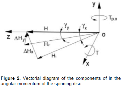
The action of the external load torque T around axis ox on the spinning disc leads to the change in the location of the vector of the angular momentum H on the small angle γx represented by the vector H1. The value of H1 is less of than that of H on the value of the change in angular momentum ΔHx. The latter is acting around axis oy and changes in the location of the vector H on the angle γy. The value of the new vector H2 is less than the vector H on the value of the ΔHy. The action of the torques ΔHx and ΔHy is simultaneous and expresses the changes in the values of the angular momentum of the spinning disc around axes ox and oy. This simple example demonstrates the redistribution of the value of the angular momentum of the spinning disc along the axes ox and oy of the rotation by the principle of the conservation of the angular momentum. These principles are confirmed by the following statements. The absence of the spin of the gyroscope’s disc means the absence of its kinetic energy and hence the inertial torques around axes. The gyroscope rotates around the axes under the action of the system of the inertial torques that consumes the part of the potential and kinetic energies of the spinning disc. The total value of the kinetic energies of the gyroscope about the axes is constant according to principles of energy conservation. The interrelations of the kinetic energies along the axes indirectly expresses the ratio of the angular velocities ωy = (4π2 + 17) ωx of the motions around the axes for the gyroscope of the horizontal location (Usubamatov, 2016). The absence of the rotation of the gyroscope around axis oy (ωy = 0) means ωx = 0, that is, the absence of kinetic energies and the inertial torques acting around these axes. The angular velocities ωy and ωx express the kinetic energies of the gyroscope rotation which are parts of the kinetic energy of the spinning disc.
From the previous discussion, the angular velocity ωx of the gyroscope is the result of the action of the resisting resulting torque (ΣTr = (Tct.x + Tcr.x + Tin.y + Tam.y) and external torques T and Tfx. The angular velocity is a component of the inertial torques, and when its value ωx = 0, it means the resulting torque ΣTr = 0 is absent. Thus, the spinning rotor rotates around axis ox acting under action only the external load and frictional torques. The ratio of angular velocities around two axes ωy = (4π2 + 17)ωx is not maintained. This is the reason that the rotation of the spinning disc under the action of the external loads around axis ox does not generate new inertial torques that demonstrates the practical tests.
The values of the torques computed by the theoretical Equations 2 and practical Equations 3 for horizontal position (γ =0) of the gyroscope enable demonstration of the true mathematical model. Substituting the components of inertial torques (Usubamatov, 2018) load and frictional torques into right side Equations 2 and 3 gives the values of the resulting torques. For Equations 2, the resulting torque is as follows:
For Equation 3, the resulting torque is presented by the right side of Equation 8. The data obtained above (Case study and practical tests), while computing the angular velocity ωx of the gyroscope around axis ox by Equation 14 for the time of turn until horizontal position, t = 1.47 s, ωx = 0.373846 rad/s, and substituting into Equations 24 and 8 give the ensuing results. The resulting torques computed by Equations 24 and 8 are as follows respectively:
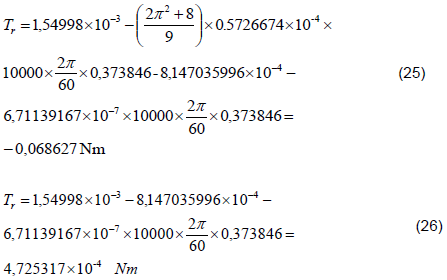
Equation 26 demonstrates that the value of the inertial torques generated by the centrifugal and Coriolis forces is bigger than other components and resulting torque acting in the clockwise direction. It is impossible because the inertial torques is constraining torques. This result validates that the mentioned inertial torques are deactivated when the gyroscope motion is around one axis. The precession torque is presented by the change in angular momentum (Tam), which is the last component of Equation 24. The precession torque (Tin) of the common inertial force is not included in Equation 24; its value dramatically increases the time of the gyroscope turn and does not validate the time of the practical test.
The deactivation of the gyroscopic inertial torques generated by the rotating mass elements occurs according to the physical principle of the kinetic energy conservation for the rotating objects. The kinetic energy of the spinning rotor along axis oz is conserved and the action of the external torque activates the change in the angular momentum at any conditions. The conducted analysis explains the physics of the deactivation of the inertial torques generated by the rotating mass elements of the spinning disc and confirms the principle of the conservation of its angular momentum.
The phenomena associated with deactivation of the gyroscopic inertial torques are very difficult to perceive against the background of generally accepted knowledge of classical mechanics. Rejection of the deactivation of inertial forces is explained by the traditional examples in known publications that consider simple mechanisms and schemes of acting inertial forces on some objects. The work of a gyroscope is not a simple process and is the reason why the solutions for its acting inertial forces and motions by researchers could not be found for centuries. As presented above, explanation of the deactivation of the gyroscopic inertial torques is also not ordinary and needs deep analysis and comprehension. Nevertheless, the described physics of the deactivation of the inertial torques do not claim to be the ultimate truth in the area of dynamics of rotating objects.
The numerous publications for computing the inertial forces acting on the spinning objects consider examples with motions of the object around one axis. These examples are suitable for the simple solution by the action of the change in angular momentum. The authors of these publications did not know about the complexity of the action of the inertial torques on spinning objects and about the deactivation of them but presented the correct solutions. However, the publications that consider the complex motions of the gyroscopic devices present wrong solutions for the action of the inertial torques. The action of the system of interrelated inertial torques should be used for solutions of the complex gyroscopic problems in engineering. A solution to such examples represents a good educational process in Engineering Mechanics which is part of the dynamics of rotating objects.
CONCLUSION
The present study on gyroscopic effects has brought breakthrough innovations in the area of the gyroscope theory. Newly defined interrelated inertial torques acting on a spinning disc of the gyroscope should be used in deriving the true mathematical models for the gyroscopic effects. An application of the new analytical solutions demonstrates the necessity to consider accurately the value of each component of the mathematical models for gyroscopic motions. The interrelated action of the inertial torques demonstrates unknown properties where one of them is the deactivation of the inertial torques generated by the rotating mass elements.
This phenomenon contradicts principles of physics and requires in-depth study and explanation of the nature of the deactivation of the part of the gyroscopic inertial torques. The torque of the change in angular momentum is acting constantly at any conditions of gyroscopic operation. These gyroscopic properties can be explained by the principle of energy conservation that is validated by the practical tests.
CONFLICT OF INTERESTS
The authors have not declared any conflict of interests.
ACKNOWLEDGEMENT
This work is supported by the Kyrgyz State Technical University, Kyrgyzstan.
NOMENCLATURE
a, d, h, ri, geometrical sizes of the gyroscope components; G, mass of the counter-weight; g, gravity acceleration; e, base of the natural logarithm; f, coefficient of sliding friction; I, index for axis ox or oy; J, mass moment of inertia of the rotor’s disc; Ji, mass moment of inertia of the gyroscope around axis I; l, distance between the gyroscope center mass and axis of the support; lm, distance between a gyroscope component center mass and axis of the support; s, mass of the axle; T, load torque; Tam.i, torque of the change in the angular momentum acting around axis I; t, time; M, mass of the gyroscope; α, δ, τ, constructional angles of the gyroscope stand; γ, angle of inclination of the rotor’s axle; ω, angular velocity of the rotor; ωi , angular velocity of precession around axis I;
REFERENCES
|
Armenise MN, Ciminelli C, Dell'Olio F, Passaro VMN (2010). Advances in Gyroscope Technologies. Springer Science and Business Media. |
|
|
Aardema MD (2005). Analytical Dynamics. Theory and Application. Academic/Plenum Publishers, New York. |
|
|
Deimel RF (2003). Mechanics of the Gyroscope. Dover Publications Inc. New York. |
|
|
Engineering ToolBox (2004). Friction and Friction Coefficients for various Materials. |
|
|
Ferrari JA (2006). Gyroscope's Precession and the Principle of Equivalence: Reply to O. Groen. Annalen der Physik (Leipzig) 46(5):399-400. |
|
|
Greenhill G (2010). Report on Gyroscopic Theory. General Books LLC, London. |
|
|
Gregory DR (2006). Classical Mechanics. Cambridge University Press, New York. |
|
|
Klein F, Sommerfeld A (2008). The theory of the top. I - IV. New York, NY: Springer. Birkhäuser, pp. 2008-2014. |
|
|
Peters CA (2001). Statistics for Analysis of Experimental Data. Environmental Engineering Processes Laboratory Manual pp. 1-25. |
|
|
Scarborough JB (2011). The Gyroscope Theory and Applications. Nabu Press, London. |
|
|
Taylor JR (2005). Classical Mechanics. University Science Books, California, USA. |
|
|
Taylor JR (1996). An Introduction to Error Analysis: The Study of Uncertainties in Physical Measurements. 2nd ed. University Science Books, Sausalito, California, USA. |
|
|
Usubamatov R (2018). Inertial Forces Acting on Gyroscope. Journal of Mechanical Science and Technology 32(1):101-108. |
|
|
Usubamatov R (2018). Deactivation of gyroscopic inertial forces. AIP Advances 8(11):115310. |
|
|
Usubamatov R 2016). A Mathematical Model for Motions of Gyroscope Suspended from Flexible Cord. Cogent Engineering 3(1):1245901. |
|
|
Usubamatov R (2015). Physics of Gyroscope Motion about One Axis. International Journal of Advancements in Mechanical and Aeronautical Engineering 2(1):55-60. |
|
|
Weinberg H (2011). Gyro Mechanical Performance: the most important parameter. Technical Article MS-2158, Analog Devices, Norwood, MA pp. 1-5. |
|
Copyright © 2024 Author(s) retain the copyright of this article.
This article is published under the terms of the Creative Commons Attribution License 4.0


